Please read my license notice before copying my photos.
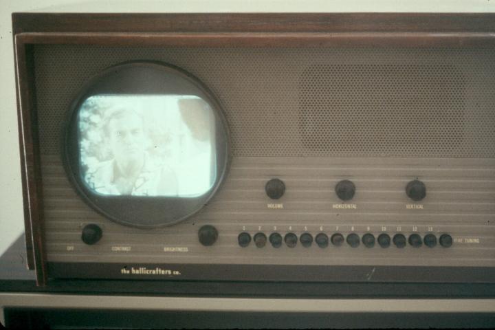
I bought this set for $20 in 1986 from a TV shop in Medford and restored it. It was manufactured in 1948. It gets channel 1 and has push-button tuning, like an old car radio. When I got it, it was literally a basket case, with many of the smaller parts stored in a picnic basket.
First stop was the Boston Public Library for a copy of the Sam's Photofact. After a thorough cleaning I made a few repairs. The tuner spring was too weak from age to function, and I replaced it with a hardware store spring. After replacing the electrolytic capacitors in the power supply and re-assembly I tried powering it up. The selenium rectifier immediately smoked and I replaced it with another one, just to be historically accurate. After that there was no smoke, and I was even rewarded with a very weak raster, but no sound or video.
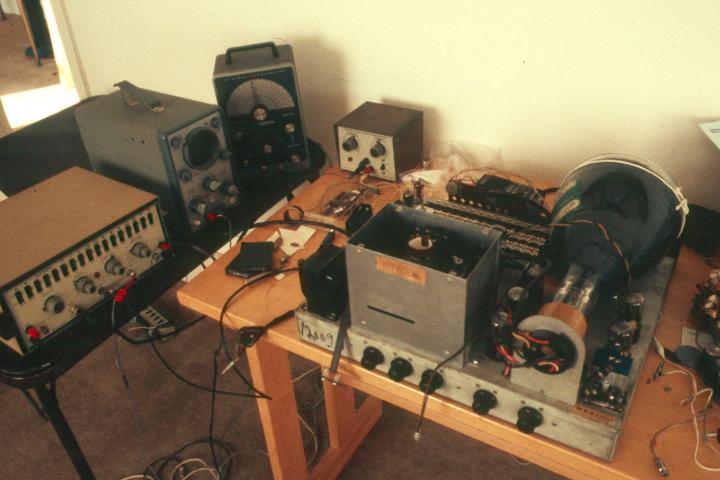
Several hours of troubleshooting revealed that many of the capacitors were bad. I ended up replacing most of them. The set was also in desperate need of an IF sweep. This set has a 27 MHz IF, unlike the modern standard of 45 MHz. I had to modify my sweep generator to make it cover this band.
Eventually I got sound and picture, but the raster was extremely weak, unviewable unless the room was completely dark. My tester showed almost no emission from the picture tube, and the HV was only 1600v, much less than the rated 5Kv.
Boston is a great place for finding parts for old TVs. I called around and discovered that someone from Florida had bought up all the 7JP4 picture tubes in town less than six months earlier. One shop had sold him 22 tubes, but had one left that the Florida man didn't want because there was a tiny bubble in the face. It looked like the bubble wouldn't interfere with the picture so I bought it. The face plate in the TV was old acrylic, and was scratched and yellowed with age, so I replaced it with new acrylic.
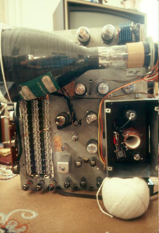
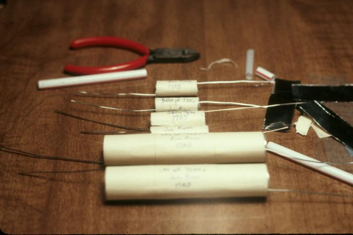
The HV was harder. There were multiple problems, which made diagnosis difficult. This set uses electrostatic deflection, and two pairs of 6000 volt paper capacitors to block the HV from the sweep circuits. I was unable to buy these capacitors and decided to make them instead.
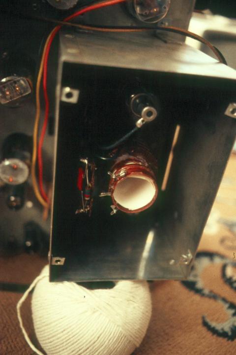
The CRC Handbook of Chemistry and Physics was indispensable here. It had a formula for capacitance given thickness, area, and dialectric constant, and it had tables giving physical and electrical properties for various materials. It was obvious from the tables that polyethylene was the proper material. Given the desired breakdown voltage (plus a margin) it was easy to determine the required thickness, then calculate the required surface area. I used tin (not aluminum) foil for the electrodes, a paper outer cover, and silicone to seal the ends. The resulting capacitors worked well and were within 10% of the calculated value.
The new capacitors helped but the picture was still weak and the HV a bit low, about 4200 volts. Inspection in a dark room revealed that the HV transformer was leaking. Unlike modern sets that use the horizontal sweep for the input to the HV section, this set has a separate oscillator that runs at much higher frequency, and an air core transformer.
I couldn't find an exact replacement but I found one with the same diameter and number of turns on the secondary. So I cut both transformers in half and combined the old primary with the new secondary, gluing them together with silicone and insulating with Krylon®.
This worked very well. A bit more adjusting and some cosmetic cleanup and I was done. As of this writing, 17 years later, this set still works fine.
For a better and more detailed description of another Hallicrafters 505 restoration, see Hallicrafters Model 505 (T-54) Television (1948).
On a slightly related topic, I got a big kick out of this story of an
RCA TK-41 color television camera.